Next picture
Top hoist page
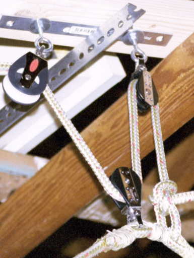 Here's the suspension. There are two of these. Each consists of a
fixed loop around the box, attached at a fixed point to a pulley, and
a nearby point to a rope. The rope goes up through one pulley, down
through the pulley on the loop, up through a third pulley, and on to
the pulley by the crook of the V.
Here's the suspension. There are two of these. Each consists of a
fixed loop around the box, attached at a fixed point to a pulley, and
a nearby point to a rope. The rope goes up through one pulley, down
through the pulley on the loop, up through a third pulley, and on to
the pulley by the crook of the V.
The ends of the loop are lashed together and cemented with epoxy.
How does epoxy stand up under shear forces? I don't know. Each
rope is only supporting 30 pounds, so we're not demanding much from
the system. I think the other rope is attached with a bowline knot.
If I had constructed it, the loop and the rope would have been the
same rope, tied with a bowline. Bill constructed it. Matter of
taste.
The original design had one pulleys. One rope was attached to the
beam, went straight down under one side of the box, straight up from
the other side, and through a pulley. The rope was supposed to slide
under the box as the box was lifted. Unfortunately the box didn't
slide at it was lifted. It rolled instead. This design also required
the horizontal bars to be parallel, making it hard to pull the ropes.
The final design had these important points. The rope around the
box does not have to slide. The loop is held by a single point at the
top, so the box has no motive to roll. There are three ropes going up
and down at the suspension, which gives a mechanical advantage. (Bob
only has to pull 1/3 the weight of the box, but three times the
distance). All the attachments at the top are basically at one
point. That keeps the suspension ropes about vertical even when the
box is fully hoisted (important because shallow angles reduce the
mechanical advantage). Having the suspension hung from one point also
allows the horizontal bars to lie on a line that is not coplanar with
the loop.
Next picture
Top hoist page